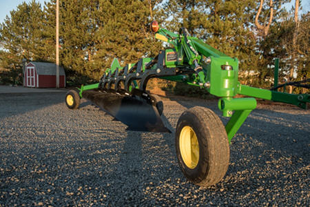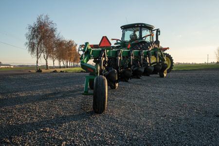
3710 MOLDBOARD PLOW
Moldboard Plow
- High clearance handles heavy residue levels
- Coulter mounting arms
- Operator's manual storage container
- Shear-bolt coulters suited for areas without rocks
View Product Brochure
Features
 Frame clearance for residue
Excellent fore-aft and vertical clearance between standards (arrows above) allows the soil and residue to freely flow through the plow:
- Both rigid and flex plows are designed to handle tall and heavy residue levels.
Clearance
Fore and aft | Vertical |
| |
864 mm (34 in.) | 851 mm (33.5 in.) |
The operator can change the plow's width of cut to match the tractor horsepower and soil conditions.
- Narrow in tough soil
- Wider in lighter soil
3710 Rigid Plow
The rigid plow has a width-of-cut range of 356 mm to 559 mm (14 in. to 22 in.) on land and 508 mm to 559 mm (20 in. to 22 in.) in furrow.
- Economical manual adjustment (turnbuckle is standard equipment)
- Convenient hydraulic cylinder adjustment is optional
- Pointer and decal allow returning to a predetermined width of cut
3710 Flex Plow
 3710 Flex Plow
The flex plow has 356 mm to 559 mm (14 in. to 22 in.) of cut.
Adjustments are made by adjusting two turnbuckles (arrows) to a predetermined length specified in the operator's manual.
The rigid model uses a scissor-type landing adjustment to set the first bottom in relationship to the rear tractor tire for the different widths of cut:
- Design uses minimum space, gives a clean-style appearance, and has a full range of adjustment.
- Economical turnbuckle is used to make the adjustment.
- Operator-supplied 76-mm x 203-mm (3-in. x 8-in.) American Society of Agricultural Engineers (ASAE) tie-bolt hydraulic cylinder may be used in place of a turnbuckle for in-furrow applications.
 Depth stops are used for easy adjustment of depth
 Land wheels help to stabilize the plow in both the working and transport positions. They also control the depth of plowing and work in conjunction with raising and lowering the plow.
Land wheels on rigid plows are tied to the Adjust-O-Cut bar for automatic setting for each width of cut.
A single wheel is standard on the six-bottom model; dual wheels are standard on the seven- and eight-bottom models and optional on the six-bottom model (recommended in softer soils).
- Provides good trailing characteristics in transport.
Land wheels on flex plows have four adjustment positions (arrow) to allow setting the assembly for 406-mm, 457-mm, or 508-mm (16-in., 18-in., or 20-in.) widths of cut or transport:
- Depth stops are used for easy adjustment of the depth.
Dual, staggered Walk-Over wheels are standard on flex plows:
- Allow the plow to trail like a cart
- Distribute weight evenly between both wheels
- Minimize bulldozing in soft soil
- Allow better residue flow
- Walk over obstacles and across dead furrows
The double-pivot design of the spring-reset standard uses tension spring force to return the standard to the working position.
- For heavier-duty applications
- Positive reset
- Non-adjustable trip force; factory set at 2727-kg (6000-lb) nominal
- Floats over buried rock
- Unhooks from ledge rock
Safety-trip standards provide an economical means for protection—suited for areas without rocks:
- No backing to reset, just raise
- Shim-adjustable trip force
- 2727-kg (6000-lb) nominal trip force (set at the factory)
- Smooth surfaces for good residue flow
- Few moving parts equals high reliability
The NU bottoms are set behind the mainframe to prevent the mainframe from becoming a pinch-point for residue. They are designed for light draft and high-speed plowing.
- Operators often find they can plow a gear higher than with competitive plows
- Greater productivity and fuel economy
- Speeds up to 10 km/h (6 mph)
Available in 400-mm (16-in.) and 450-mm (18-in.) sizes with an unpolished finish.
The maximum plowing depth are as follows:
Bottom maximum | Plowing depth* |
|---|---|
400 mm (16 in.) | 305 mm (12 in.) |
450 mm (18 in.) | 356 mm (14 in.) |
* In some soil conditions at plowing depths in the 254-mm to 356-mm (10-in. to 14-in.) range, soil may boil over the moldboard, resulting in poorly defined furrows.
Shares for NU bottoms
Both the NU 400 and the NU 450 come standard with heavy-duty, full-cut shares.
 Variety of shares
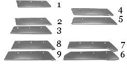
A variety of shares are available through Parts to match the plowing conditions:
Image | Part | Description |
1 | NU400 | Regular, narrow cut |
2 | NU400 | Heavy duty, narrow cut |
3 | NU400 | Heavy duty, full cut |
4 | NU450 | Heavy duty, narrow cut |
5 | NU450 | Heavy duty, full cut (standard equipment) |
6 | NU450 | 500-mm over-cut (for use when wide widths of cut or complete slicing is required) |
7 | NU450 | Hard-faced gumbo (for heavy soil conditions when penetration is a problem |
8 | NU400 | Hard-faced (for areas where abrasive soil causes rapid wear of heavy-duty shares—not for use in rocks) |
9 | NU450 | Hard-faced (for areas where abrasive soil causes rapid wear of heavy-duty shares—not for use in rocksfor) |
The gumbo moldboard (A32211) is available for NU 400 bottom and is recommended for use in heavy soil (gumbo) conditions. It is similar to the NU 400 bottom except that it has less area at the wing tip.
- Moldboard will not be forced upward by soil movement as much as NU 400.
- Permits soil to push off easier for better scouring and lighter draft.
John Deere furnishes a replacement share for any John Deere plow share that breaks before the share reaches the following wear limits (labor not included; wear to be measured perpendicularly across the middle of the front bolt hole):
- 13-mm (1/2-in.) wear, 89 mm (3.5 in.) remaining.
Trashboards for NU bottoms
 Trashboard
Plastic or steel trashboards can be added to NU bottoms to improve coverage in tall, heavy residue. Plastic trashboards are only recommended for non-abrasive soils where scouring is a problem with steel trashboards.
 Shear-bolt coulters
Economical design of the shear-bolt coulters is suited for areas without rocks:
- Few moving parts
- Good depth adjustment range
- Good lateral adjustment range
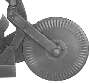
Adjustable-force cushion coulters are suited for rocky or normal field conditions:
- Excellent rosette depth adjustment range
- Good lateral adjustment range
- Separate down-force adjustment
- Overload protection to prevent damage
Specifications
Compare the specifications of up to 4 models
| Key Specs | 3710-moldboard-plow Current Model |
|---|---|
| Total width of cut | |
| Option 1 | Rigid plow On land: 356 to 559 mm 14 to 22 in. In furrow: 508 to 559 mm 20 to 22 in. |
| Option 2 | Flex plow: 356 to 559 mm 14 to 22 in. |
| Option 3 | |
| Option 4 | |
| Plowing depth | 305 mm 12 in. 356 mm 14 in. |
| Horsepower required - Option 1 | |
| Option 2 | |
| Option 3 | |
| Option 4 | |
| Hitch | |
| Type | |
| Steering | Integral, in-furrow No Integral, on-land No Semi-integral, on-land No Drawn, in-furrow Yes: 6, 7 Drawn, on-land Yes: 6, 7, 8, 9, 10 |
| Reversible | No |
| No. of bottoms | |
| Option 1 | 6 |
| Option 2 | 7 |
| Option 3 | 8 |
| Option 4 | 9 |
| Option 5 | 10 |
| Option 6 | |
| Option 7 | |
| Option 8 | |
| Total width of cut | |
| Adjustment | Standard: Manual Optional: Hydraulic |
| Option 1 | Rigid plow On land: 356 to 559 mm 14 to 22 in. In furrow: 508 to 559 mm 20 to 22 in. |
| Option 2 | Flex plow: 356 to 559 mm 14 to 22 in. |
| Option 3 | |
| Option 4 | |
| Option 5 | |
| Option 6 | |
| Option 7 | |
| Option 8 | |
| Weight (approximate) | |
| Option 1 | |
| Option 2 | |
| Option 3 | |
| Option 4 | |
| Option 5 | |
| Option 6 | |
| Option 7 | |
| Option 8 | |
| Clearances | |
| Vertical | 851 mm 33.5 in. |
| Fore-aft | 864 mm 34 in. |
| Standards | |
| Shearbolt | No |
| Safety trip | Yes |
| Spring reset | Yes |
| Hydraulic | No |
| Coulters | |
| Option 1 | Yes |
| Option 2 | Yes |
| Option 3 | |
| Bottoms | |
| Option 1 | Plowing depth 305 mm 12 in. 356 mm 14 in. Reversible bottom - steel: 406 mm 16 in. |
| Option 2 | Reversible bottom - steel: 450 mm 18 in. |
| Option 3 | |
| Option 4 | |
| Option 5 | |
| Option 6 | |
| Frame | |
| Option 1 | 203x203 mm 8x8 in. |
| Option 2 | |
| Option 3 | |
| Expandable | No |
| Horsepower required | |
| Option 1 | |
| Option 2 | |
| Option 3 | |
| Option 4 | |
| Landing | |
| Type | |
| Gauge wheel | |
| Type | |
| Tires | |
| Type | |
| Trashboards | |
| Type | |
| Additional features | |
| Options |


