
1835 AIR HOE DRILL
Air Hoe Drill
- Choice of ground-engaging openers
- Parallel Tracking™ or AutoTrac™ compatibility
- Focused on proper air hose routing
- Additional operators manuals and decal kit
View Product Brochure
Features
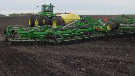 Side-to-side flexibility demonstrated by 1830
Most producers view purchasing a seeding system as a long-term investment. The life requirement of these robust machines is four times longer than previous models. That is why the John Deere seeding group has built even more durability into the 1830 and 1835 Air Hoe Drills.
An advanced and rigorous testing program has proven the machine durability to the extent that John Deere now offers a three-year frame warranty with each 1830 and 1835 that rolls out of the factory.
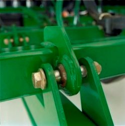 Robust ball joints
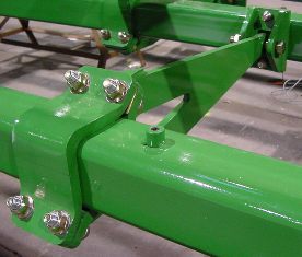 Cast rank tube connectors
Robust ball joints connect strong fore-aft tubes to 100-mm x 100-mm (4-in. x 4-in.) rank tubes, which are joined to one another by pivoting rank connectors. Both the mainframe and wing sections share this durable construction that enables the frame to flex diagonally, relieving stress on solid frame members and avoiding frame failures.
Seed smart with confidence that the 1830 and 1835 will endure the field conditions.
Seed depth uniformity
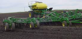 Diagonal frame flexibility keeps openers engaged
Producers are more attuned to the importance of seed depth than ever before. A uniform-looking field is not the only goal; yield is too. Proven yield penalties across the world range from 5 percent to 25 percent, depending on depth variance.
The 1830 and 1835 feature diagonal mainframes and wing flexing – helping openers maintain their depth over uneven terrain.
Setting depth is one of the most critical adjustments an operator will make to a seeding tool. John Deere understands every operator needs dependable, repeatable depth control that is easily adjustable. Not every producer agrees on how to make it. That is why John Deere provides a choice of two depth control options on the 1830 and 1835.
Mechanical depth shims are repeatable and reliable
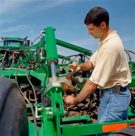 Adjusting mechanical depth shims
Often-heard are comments from producers who say they prefer the positive mechanical depth control offered by the 1820. This popular concept is base equipment on the 1830 and 1835 air hoe drills.
Two indexed depth shim packs on the mainframe are not only easy to set, but reduce the number of adjustment sites over previous designs by up to 60 percent.
Less time adjusting means more time seeding.
TouchSet™ depth control
Changing field conditions such as moisture levels and soil types can make setting depth a challenge. TouchSet depth control makes adjusting depth in response to changing field conditions easy and profitable. On 8R and 9R Series tractors, the operator uses selective control valve (SCV) #1 and the SCV TouchSet control panel to perform all the depth control functions from the seat. Considering yield penalties of 5 percent due to seeding 2.5 cm (1 in.) too deep or too shallow, the convenience of in-cab adjustment pays nicely.
NOTE: Repeatability is +/- 6 mm (0.25 in.) to preset depth. If your seeding operation requires accuracy greater than +/- 6 mm (0.25 in.), the use of shim packs is recommended.
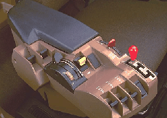 Control arm
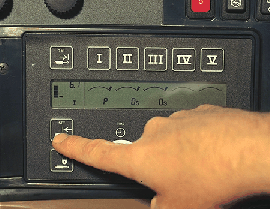 CommandCenter™
How does it work? The operator uses the TouchSet (SCV setup panel) to set or change the operator depth.
- With the implement nine-pin connector connected to the tractor, start the tractor; a P will appear in the window of the control panel under SCV #1.
- The remote sensor located on the rockshaft monitors position of the implement.
- After operating depth is measured at the ground engaging tool and the desired depth obtained, press the lower set button on the control panel. That depth is now set.
- On-the-go depth changes can be made by touching the set button to select a new depth.
- Implement raise height selection uses the upper set button on the control panel to preset the distance the implement is raised above the operating depth.
Preset the raise height to:
- Take out wheel tracks on headlands
- Limit raise height for waterway crossings
- Manual depth override capacity
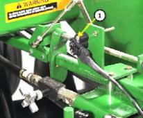 Remote position sensor
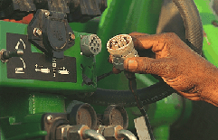 Electrical connector
A remote position sensor (1) is located at the rear of the drill; electronically monitors the positions of the implement.
An electrical connector is used for easy hookup of TouchSet depth control sensor on the implement to the tractor system (8R Tractor illustrated).
NOTES:
- For use with all 8R and 9R (or older models) Series John Deere tractors.
- TouchSet depth control requires additional tractor parts for hookup; see appropriate tractor section in this Sales Manual.
1830
Code | Bundle | Description |
2500 |
| Positive mechanical depth control |
2505 |
| TouchSet depth control plus positive mechanical depth control |
1835
Code | Bundle | Description |
2510 |
| Positive mechanical depth control with active hydraulic down-pressure system for separate fertilizer placement (SFP) |
2515 |
| TouchSet depth control and positive mechanical depth control with active hydraulic down-pressure system for SFP |
Fertilizer inputs can represent 30 percent to 35 percent of the cost in small-grain and oil seed production. It is no wonder producers are concerned about nitrogen losses from gas escape, volatilization, and leaching.
Nitrogen loss pathways
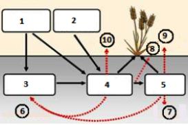 Manage nitrogen to minimize losses
- Manure and crop residues
- 46-0-0
82-0-0
28-0-0 (75 percent) - Soil organic N
- Ammonium NH4+
- Nitrate NO3+
- Immobilization
- Leaching and runoff
- NO
N2O - N2+
N20 Denitrification - NH3 Volatilization
Nitrogen (N) loss occurs via four key pathways.
- Volatilization of anhydrous ammonia (NH3) into the atmosphere.
- Immobilization, or the uptake of nitrogen by microbes breaking down residue.
- Leaching or runoff of N2 or NO2 (nitrite).
- Volatilization of N2 or NO2 (nitrite).
Denitrification is the conversion of nitrate (NO3) to nitrite (NO2), and eventually to N2 or N2O (nitrous oxide). These nitrogen forms are not held by the soil complex like NO3 and NH4 and are subject to escape via water.
SFP opener prevents nitrogen loss
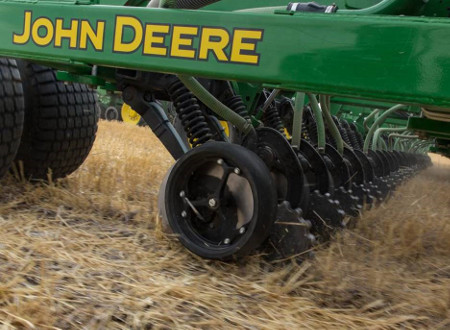 SFP opener
The SFP opener features:
- Single-disk blade slices through the soil at a five-degree angle
- Opener is adjusted via active hydraulic-down pressure
- Depth gauging is accomplished at the opener
- Closing wheel ensures fertilizer stays where it is applied
Ultra-low soil, moisture, and residue disturbance, plus the cast closing wheel, are able to lock in dry, liquid or gaseous fertilizer.
IMPORTANT: Furrow closing wheels are required when applying anhydrous fertilizer.
Plus, application at seeding means no more worrying about pre-season nitrogen loss due to de-nitrification and leaching. Reduce dependence on risky top-dress applications where volatilization and immobilization can significantly reduce crop uptake. Fertilizer can now be applied in the seeding operation with confidence, knowing it is firmly in place where it belongs in the soil.
Researchers observed stand reductions up to 5 percent in wheat and 26 percent in canola (PAMI 738) when nitrogen fertilizer was placed near the seed. Those are the risks and possible consequences for nitrogen application too close to the seed.
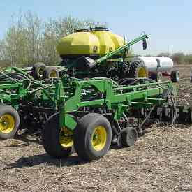 1835 seeding wheat and applying ammonia separately
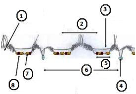 1835 with SFP, 10.2-cm (4-in.) points and 10.2-cm (4-in.) packers
- Undisturbed soil
- 25.4 cm (10 in.)
- Disturbed soil packed over seed row
- SFP nitrogen
- 10.2 cm (4 in.)
- 50.8 cm (20 in.)
- Seed
- Seep-placed phosphorus
John Deere seeding group thinks sound nitrogen management should be rewarded. That is why the 1835 SFP Air Hoe Drill was designed with the exclusive SFP opener to place nitrogen, potassium and sulfur-based fertilizers separate from the seed. This positive separation of fertilizer and seed eliminates seedling damage caused by some fertilizer forms and application methods.
Understanding distance between seed and fertilizer placement
When seeding with the 1835 SFP, the seed opener will have an effect on the distance between the seed and fertilizer. For example, as the diagram above shows, seeding with a 10.2-cm (4-in.) spread places the seed between 20.3 cm (8 in.) and 30.5 cm (12 in.) from the fertilizer in the same furrow.
NOTE: Narrow spread openers are recommended to keep a consistent distance between seed and fertilizer.
IMPORTANT: The 1835 SFP is also capable of applying safe rates of starter fertilizer with the seed.
Nitrogen application timing
 Manage nitrogen to minimize losses
- Manure and crop residues
- 46-0-0
82-0-0
28-0-0 (75 percent) - Soil organic N
- Ammonium NH4+
- Nitrate NO3+
- Immobilization
- Leaching and run off
- NO
N2O - N2+
N2O De-nitirfication - NH3 Volatilization
The United States Department of Agriculture (USDA) data suggests spring wheat producers who apply nitrogen at seeding typically cut their application rates by 15 percent when compared to pre-seeding applications. This is driven by the reduced risk of environmental loss.
Ammonium (NH4) can eventually transform to the nitrate (NO3) form of nitrogen. The longer the nitrate form of nitrogen is exposed to wet soil conditions, the more of it is converted to nitrite (NO2) and other lesser oxidized forms of nitrogen through denitrification. These nitrogen forms are very unstable and are subject to leaching through the soil profile, rendering them unavailable to the crop. To compensate for this potential loss of nitrogen, it is recommended to apply 15 percent more nitrogen in the fall.
Applying anhydrous ammonia at seeding, close to the time of crop uptake, can, in fact, reduce the actual amount of applied nitrogen to achieve a given yield. Given a rate of 18-kg (100-lb) of nitrogen per hectare, a price of 10 cent per kg ($0.30 per pound), and when used in an application over 1200 ha, the nitrogen rate is cut by 15 percent, which means a cost saving of 10.800 Euro ($13,500).
Nitrogen sources
Most years, producers can save 10 percent in their nitrogen costs by using low-cost, concentrated anhydrous ammonia (NH3) instead of granular urea.
Example:
- 3000 acre farm
- Nitogren at 85 lb / acre
- $0.03 differential in cost
- Results in savings of $7,650
Fertilizer inputs can represent 30 percent to 35 percent of the cost in small grain and oil seed production. It is no wonder farmers are concerned about nitrogen losses from gas escape, volatilization and leaching.
One opener combines four key processes to minimize nutrient losses through precise nutrient placement at seeding. John Deere’s SFP disc opener features:
- Active hydraulic downforce
- Depth gauging at the opener
- Ultra-low soil and residue disturbance
- Positive closing system
All of these lock in dry, liquid, or gas forms of nitrogen.
There is no more worrying about pre-season nitrogen loss due to denutrification and leaching. Operators can forget about volatilization of top-dress applications, and maybe most notably, endure a day of seeding without the burning nasal passages that accompany poor anhydrous ammonia retention.
SFP opener with 5-degree angle
 SFP opener
Key features of the opener include:
- Depth gauging at the opener with 11.4-cm (4.5-in.) or 7.6-cm (3-in.) semi-pneumatic gauge wheels
- Depth adjustments are in 6 mm (1/4 in.) increments from 1.3-cm (1/2-in.) to 9-cm (3-1/2-in.) deep
- 5-degree operating angle creates a narrow trench and minimizes soil disturbance
- Close-coupled closing wheel assembly for quick trench closure and maximum fertilizer retention
- NOTE: Closing wheels are base equipment on anhydrous openers and optional on liquid and dry openers. Closing wheels are recommended.
- Extended-wear (chrome alloy) fertilizer boots
- Sealed, non-greaseable bearings
Fertilizer tubes
There are four choices of interchangeable fertilizer tubes:
A) Dry fertilizer tube to be used with 32-mm (1-1/4-in.) secondary fertilizer hose from the 1910 Commodity Cart.
B) Liquid fertilizer tube (for 13-mm [1/2-in.] ID hose). Using this tube for anhydrous may cause loss of retention.*
C) Dual fertilizer delivery tube. Allows for placement of dry or anhydrous. If applying both simultaneously, the operator may need to provide a relief system to relieve air from dry tube for adequate anhydrous retention. Without air relief, the operator will need to adjust air plenum to restrict all airflow to SFP dry tubes when anhydrous is being applied.*
D) Anhydrous tube (for 10-mm [3/8-in.] ID hose).*
* NOTE: Liquid or NH3 Fertilizer metering/delivery system is not provided by the John Deere seeding group.
Code | Bundle | Description |
| 1205 | Dry fertilizer delivery tube | |
| 1215 | Liquid fertilizer delivery tube | |
| 1220 | Dual delivery tubes | |
| 1225 | Anhydrous fertilizer delivery tube |
Opener gauge wheel
11.4-cm x 40.6-cm (4.5-in. x 16-in.) semi-pneumatic wheel gauges depth
- Standard smooth plastic hub for minimal soil disturbance in mellow soils
- Depth can be controlled from 0.6 x 9 cm (1/4 to 3-1/2 in.) in 6-mm (1/4-in.) increments (13 total adjustments)
- Runs on sealed, double row tapered ball bearings
7.6-cm x 40.6-cm (3-in. x 16-in.) gauge wheel (optional)
- Less stubble or residue disturbance
- Depth can be controlled from 0.6 to 9 cm (1/4 to 3-1/2 in.) in 6-mm (1/4-in.) increments (13 total adjustments)
Code | Bundle | Description |
| 1605 | Smooth-side gauge wheel | |
| 1610 | Narrow gauge wheel (7.6 cm [3 in.] in width) |
Opener furrow closing wheel
2.5-cm x 30.5-cm (1-in. x 12-in.) cast closing wheel follows the press wheel to close furrow, placing soil over seed or fertilizer after the press wheel secures seed in furrow.
- A double-row ball bearing to reduce wear is located in the arm of the closing wheel
- Mounted parallel to the furrow opener, the closing wheel can be adjusted laterally to allow running on top of furrow for sandy or mellow soils or to side of furrow for heavier soils
- Down pressure is adjustable from 12 kg to 19.5 kg (26 lb to 43 lb) (no tools and three adjustments).
NOTE: Closing wheel is optional on fertilizer openers.
Code | Bundle | Description |
| 1701 | Less cast closing wheel | |
| 1707 | Cast serrated fertilizer closing wheel |
Serrated closing wheel
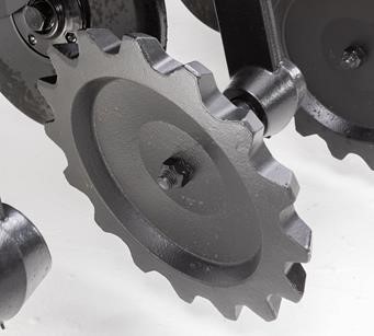 Serrated closing wheel
The serrated closing wheel offers an improved closing system when seeding in harder, dryer conditions. The notches on the wheel break up the dryer conditions while offering an improved sealing that will directly promote better germination which supports and increases flowering and even / fuller canopy overall. By sealing off the trench, there is less outgassing of anhydrous, offering a safer environment for the producer. By less outgassing, there is a higher opportunity for increased yields stemming from better germination
Transporting large machines on public roads can be a little stressful. Passing motorists, mailboxes, overhead lines, and trees can all contribute to potential hazards.
With so much to focus on, the 1830 Air Hoe Drill operator should not have to worry about openers engaging the pavement when lowering a machine to clear an overhead obstacle.
With the optional transport height reduction feature, the operator does not need to worry. This handy feature can also serve to set the height for storage inside.
How it works
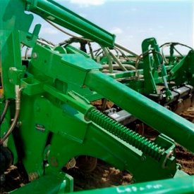 Transport height reduction assembly
Simply setting the pin in the appropriate hole will stop the machine from lowering when the openers are a safe distance above the pavement.
The operator can focus on the overhead obstacle and other hazards such as passing motorists near the machine. This can prevent a potentially damaging encounter with the road surface or even an accident.
TruPosition 250-kg (550-lb) trip force
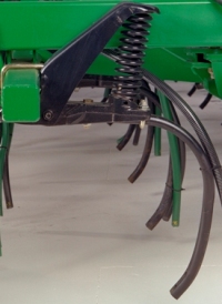 250-kg (550-lb) trip-force TruPosition standard
Unmoved
That is how John Deere's TruPosition standard may be described. When the seed depth consistency and row spacing integrity are top concerns, this low-maintenance design will not compromise.
This can translate to a more than 5 percent yield increase by maintaining seed depth in tough ground conditions. The no-bolt design means avoiding maintenance costs and damaging downtime down the road.
It has a 51-degree shank.
Harrow
Seed depth consistency is a function of initial seed placement below the soil surface and displacement of soil over the seed row. When soil throw from the openers is great enough to cover up neighboring seed rows, a harrow is recommended to level the seedbed and equalize displaced soil over all seed rows prior to packing.
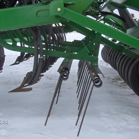 1830 with sweeps, harrow, and 14-cm (5.5-in.) packers
Equipping an 1830 with the optional two-bar harrow helps level the seedbed before packing, ensuring an even distribution of soil over all seed rows. Adjustments include both vertical and tine-pitch, allowing the operator to set the harrow for the level of aggressiveness needed to level the seedbed.
NOTE: Not recommended for seeding into surface residue levels exceeding 35 percent.
NOTE: Harrow is not compatible with 1835.
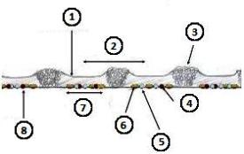 1830 on 25.4-cm (10-in.) spacing, 30.5-cm (12-in.) sweep, harrow
- Disturbed soil packed over seed row with 14-cm (5.5-in.) semi-pneumatic packer.
- 25.4 cm (10 in.)
- Tilled soil
- Seed-placed phosphorus
- Seed-placed nitrogen
- Seed
- 17.8 cm (7 in.)
- Seed floor created by sweep
The seeding profile behind an 1830 equipped with a harrow and sweeps will look similar to the image on the left. A flat seed floor with seed distributed over 50 percent of the row spacing for 25.4-cm (10-in.) configurations using the Perma-Loc™ boot and sweep.
1830:
Code | Bundle | Description |
1000 | * | 250-kg (550-lb) TruPosition opener on four ranks, less harrow |
1015 | * | 250-kg (550-lb) TruPosition opener on front three ranks, double-bar harrow |
1835:
Code | Bundle | Description |
1005 | * | 250-kg (550-lb) TruPosition opener on rear three ranks and separate fertilizer placement (SFP) disk openers on front rank |
The 1830 and 1835 feature a simplified hydraulic system due to a common rockshaft design in the lift circuit. Not only does this tie all sections together ensuring consistent depth from mainframe to wing, it also eliminates 50 percent to 67 percent of the hydraulic cylinders, reducing the chance of hydraulic failure.
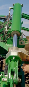 Frame lift cylinder
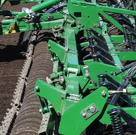 Common rockshaft design
- No rephasing of hydraulic cylinders
- Fewer hydraulic components and hoses to maintain
- Seed with confidence that all air hoe drill sections are seeding at the same depth
Knife bodies and points
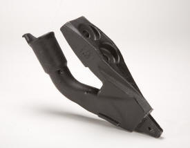 Knife body
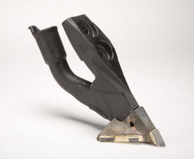 Knife body with 10.2 cm (4 in.) point
Many producers enjoy the moisture-saving benefits of low-disturbance seeding. To make it easier for them to reap the rewards of low-disturbance seeding, factory-installed knife bodies are available for 1830 and 1835 Drills.
The knife bodies are available in 2.5 cm (1 in.) or 10.2 cm (4 in.) spread points.
Use the 2.5-cm (1-in.) point for low disturbance or, if a wider spread pattern is desired to increase seedbed utilization, use the 10.2-cm (4-in.) point. The points can be quickly changed with a single roll-pin fastening system and feature carbide tips to ensure long life.
The knife bodies also feature a positive hose retention system with provisions for a hose clamp to hold the hose in place.
These knife bodies may not perform as designed in wet, sticky soil conditions.
NOTE: Points and roll pins are not included. Points and roll pins are available through Service Parts.
Perma-Loc™ spoons and sweeps
Perma-Loc spoons and sweeps from John Deere offer reduced maintenance because the Perma-Loc design enables a change-out up to five times faster than traditional bolt-on components.
They also offer cost savings because with Perma-Loc spoons and sweeps, there is no more purchasing hardware each time spoons are changed out. This can save $309 USD list price when changing out the spoons on a 18.3-m (60-ft) tool with 19-cm (7.5-in.) spacing.
Save time and money and seed smart with John Deere Perma-Loc spoons or sweeps.
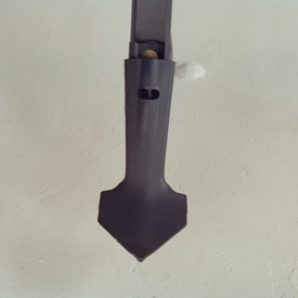 10.2-cm (4-in.) Perma-Loc spoon
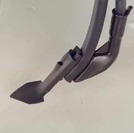 10.2-cm (4-in.) Perma-Loc spoon
Shown is the 10.2-cm (4-in.) Perma-Loc spoon; 7.6-cm (3-in.) spoons are also available.
Spoons are not included in base price and must be ordered separately.
Below is the seedbed profile that can be expected if using a 10.2-cm (4-in.) spoon in conventional tillage with the 1835 Separate Fertilizer Placement (SFP).
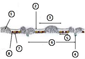 10.2-cm (4-in.) Perma-Loc spoon
- Tilled soil
- Disturbed soil packed over seed row
- 25.4 cm (10 in.)
- Separate fertilizer placement nitrogen
- 10.2 cm (4 in.)
- 50.8 cm (20 in.)
- Seed
- Seed-placed phosphorus
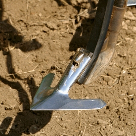 30.5-cm (12-in.) Perma-Loc sweep and boot
 Seedbed profile - 1830 and 30.5-cm (12-in.) Perma-Loc sweeps
- Disturbed soil packed over seed row with 14-cm (5.5-in.) semi-pneumatic packer
- 25.4 cm (10 in.)
- Tilled soil
- Seed-placed phosphorus
- Seed-placed nitrogen
- Seed
- 17.8 cm (7 in.)
- Seed floor created by sweep
Codes for ground-engaging openers
Code | Bundle | Description |
5000 |
| Perma-Loc clip and seed boot for TruPosition™ standard
|
5001 |
| Perma-Loc clip and seed boot for TruPosition openers with sweeps
|
5005 | * | Knife body for TruPosition standard |
5006 |
| Knife body with 2.5-cm (1-in.) tip for TruPosition openers |
5007 |
| Knife body with 10.2-cm (4-in.) tips for TruPosition openers |
5010 | * | Less ground-engaging tools and seed boot for TruPosition and spring-cushion openers |
Perma-Loc removal tool
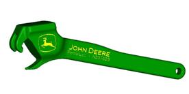 Perma-Loc removal tool
This handy Perma-Loc removal tool should be ordered for each drill ordered with Perma-Loc components.
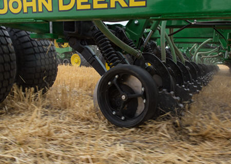 SPF Openers
Separate fertilizer placement offers nutrient placement at a 5 or 7-degree angle
The 5-degree fertilizer opener:
- Is required for liquid and anhydrous (NH3) fertilizers
- Will also apply dry fertilizer
- Opens a smaller trench than the 7-degree opener
- Is better able to capture anhydrous and liquid fertilizer and seal fertilizers in the soil
Fertilizer tubes
There are four choices of interchangeable fertilizer tubes:
- Dry fertilizer tube to be used with 32-mm (1-1/4-in.) secondary fertilizer hose from the 1910 Cart
- Liquid fertilizer tube (for 13-mm [1/2-in.] i.d. hose)
- IMPORTANT: Using this tube for anhydrous may cause loss of retention
- Dual fertilizer delivery tube – allows for placement of dry or anhydrous. If applying both simultaneously, the operator may need to provide a relief system to relieve air from dry tube for adequate anhydrous retention. Without air relief, the operator will need to adjust air plenum to restrict all airflow to SFP dry tubes when anhydrous is being applied
- Anhydrous tube (for 10-mm [3/8-in.] i.d. hose)
- Liquid or NH3 fertilizer metering/delivery system is not provided by the John Deere Seeding Group
Key features of the SFP opener are:
- 457.2-mm (18-in.) opener blades operate at 5 degrees, resulting in a narrow trench with less soil disturbance
- Fertilizer tubes are interchangeable among dry, liquid, or anhydrous (NH3)
- Closing wheel assembly is closer to the fertilizer delivery tube; provides increased fertilizer retention
- Serrated closing wheels are base equipment on anhydrous openers and optional on liquid and dry openers
- NOTE: Closing wheels are recommended when dry soil conditions are common.
- Extended-wear (chrome alloy) fertilizer boots are standard equipment
- Choice of five different gauge wheels
- Depth adjustments in 6-mm (1/4-in.) increments from 13 mm to 89 mm (1/2 in. to 3.5 in.) deep
Opener furrow-closing wheel
The 25-mm x 305-mm (1-in. x 12-in.) cast closing wheel follows the press wheel to close the furrow, placing soil over seed or fertilizer after the press wheel secures the seed in the furrow.
- A double-row ball bearing to reduce wear is located in the arm of the closing wheel
- Mounted parallel to the furrow opener, the closing wheel can be adjusted laterally to allow running on top of the furrow for sandy or mellow soils or to side of the furrow for heavier soils
- Down pressure is adjustable from 11.8 kg to 19.5 kg (26 lb to 43 lb) (no tools and three adjustments)
- A grease fitting in the pivot arm provides free movement for the arm
Specifications
Compare the specifications of up to 4 models
| Key Specs | 1835-air-hoe-drill Current Model |
|---|---|
| Spacing and width #1 | Spacing: 25.4 cm 10 in. Width: 12.5 m 41 ft |
| Spacing and width #2 | Spacing: 25.4 cm 10 in. Width: 15.2 m 50 ft |
| Spacing and width #3 | Spacing: 25.4 cm 10 in. Width: 18.6 m 61 ft |
| Spacing and width #4 | |
| Spacing and width #5 | |
| Spacing and width #6 | |
| Spacing and width #7 | |
| Spacing and width #8 | |
| Spacing and width #9 | |
| Spacing and width #10 | |
| Dimensions | |
| Road clearance with sweep | 40.6 cm 16 in. |
| Transport width | 3-section model: 6.2, 12.5 m 20.3, 41 ft 5-section model: 6.2, 6.25, 15.2, 18.6 m 20.3, 20.5, 50, 61 ft |
| Nominal mainframe width (between wing-fold pivots) | 4.19 m 13.75 ft |
| Number of seed openers | Openers link |
| Spacing and width #1 | Working width 12.2 m 40 ft Transport height without harrow 5.57 m 18.27 ft Minimum temporary height reduction with sweeps 508 mm 20 in. Weight With typical options: 13,154 kg 29,000 lb Spacing: 25.4 cm 10 in. Width: 12.5 m 41 ft |
| Spacing and width #2 | Working width 15.2 m 50 ft Transport height without harrow 4.8 m 15.75 ft Minimum temporary height reduction with sweeps 508 mm 20 in. Nominal inner wing width (between wing-fold pivots) 3.08 m 10.1 ft Weight With typical options: 17,044 kg 37,575 lb Spacing: 25.4 cm 10 in. Width: 15.2 m 50 ft |
| Spacing and width #3 | Working width 18.3 m 60 ft Transport height without harrow 5.8 m 19.02 ft Minimum temporary height reduction with sweeps 508 mm 20 in. Nominal inner wing width (between wing-fold pivots) 4.14 m 13.59 ft Weight With typical options: 18,790 kg 41,425 lb Spacing: 25.4 cm 10 in. Width: 18.6 m 61 ft |
| Spacing and width #4 | |
| Spacing and width #5 | |
| Spacing and width #6 | |
| Spacing and width #7 | |
| Spacing and width #8 | |
| Spacing and width #9 | |
| Spacing and width #10 | |
| Spacing and width #11 | |
| Spacing and width #12 | |
| Spacing and width #13 | |
| Spacing and width #14 | |
| Spacing and width #15 | |
| Spacing and width #16 | |
| Spacing and width #17 | |
| Spacing and width #18 | |
| Spacing and width #19 | |
| Seed Opener | |
| Type #1 | Spacing 25.4, 31.75 cm 10, 12.5 in. Dimensions 31.75 x 50.8 x 711 mm 1.25 x 2 x 28 in. Trip force 51 degree - 2.45 kN 550 lbf TruPosition™ - 51 degree (angle) |
| Type #2 | |
| Type #3 | |
| Penetration force | |
| Underframe clearance | 71.12 cm 28 in. |
| Fertilizer Opener | |
| Type #1 | Spacing 508 mm 20 in. Blade size 457 mm 18 in. Fertilizer compatibility Anhydrous gas, liquid, dry Rolling disk |
| Type #2 | |
| Mainframe | |
| Centerframe width | 4.19 m 13.75 ft |
| Cross members | 10.16 x 10.16 cm 4 x 4 in. |
| End tubes | 102 x 102 x 9.5 mm 4 x 4 x 3/8 in. |
| Hitch | Pin - 50.8 mm 2 in. |
| Hitch category | Category IV |
| Seeding tool depth control | Adjustable mechanical stop |
| Mainframe and wing flexibility | Diagonal flex |
| Fore-Aft Dimensions | |
| Length | Hitch pin to rear of transport wheels 10.12 m 33.2 ft Lateral frame clearance, opener to opener 76.2 cm 30 in. Fore-aft frame clearance between ranks 73.66 cm 29 in. Front of front cross member to front of rear cross member (4 ranks) 1.47 m 4.83 ft |
| Harrow | |
| Type | |
| Press Wheels | |
| Size | Steel On 10-in. spacing: 7.6 x 53.3, 10.2 x 55.9 cm (15.7, 16.3 kg) 3 x 21, 4 x 22 in. (34.7, 35.9 lb) Semi-pneumatic On 10-in. spacing: 7.6 x 53.3, 10.2 x 53.3, 14 x 53.3 cm (16.9, 19, 23.4 kg) 3 x 21, 4 x 21, 5.5 x 21 in. (37.2, 41.8, 51.6 lb) Split 36.8 kg 81.2 lb |
| Tires | |
| Tire specifications | Tire link |
| Tractor Hydraulic Requirements | |
| Minimum SCVs | 3 |
| Tractor hydraulic circuit requirements | One selective control for frame lift; one selective control for wing fold and transport wheels, one for SFP rockshaft control |
| Tractor hydraulic pressure requirement | 41-ft: 138 bar/min 2000 psi/min 50-ft: 151.7 bar/min 2200 psi/min 61-ft: 172.4 bar/min 2500 psi/min |
| Tractor Horsepower Requirements | |
| 34-ft. | |
| 41-ft. | 242.35 kW 325 hp |
| 50-ft. | 298.3 kW 400 hp |
| 56-ft. | |
| 57-ft. | |
| 61-ft. | 354.2 kW 475 hp |
| 76-ft. | |
| Warning Lights | |
| Standard | Yes |
| Freight | |
| F.O.B. | Valley City, North Dakota |
| Tractor Compatibility | |
| On-line compatibility guide |


